UPVC industrial pipe: I. Basic knowledge of PVC-U water supply pipeline
PVC-U pipe is made of hygienic polyvinyl chloride (PVC) resin as the main raw material, added with an appropriate amount of stabilizer, lubricant, filler and color enhancer, extruded by plastic extruder and injection molded by injection molding machine, and completed the production of pipes and pipe fittings through cooling, curing, shaping, inspection, packaging and other processes. Compared with the traditional pipeline, PVC-U pipeline has the advantages of light weight, corrosion resistance, small water flow resistance, energy saving, fast installation and low cost. It has been vigorously promoted and applied with remarkable benefits.
Performance characteristics of UPVC chemical pipe
1. Low price
The material cost is low, the installation cost is low, and the reduction proportion of different projects is different. For example, the cost of indoor water supply and drainage can be saved by 30%;
2. Light material
Convenient handling and installation, saving time and cost
3. Corrosion resistance
Resistant to most acid, alkali and salt (see the corrosion resistance table of UPVC products for details);
4. Aging resistance
Good chemical stability, material test and foreign engineering examples show that the actual service life of UPVC exceeds 50 years;
5. Smooth pipe wall
Low fluid resistance, no pollution, no bacteria, and low comprehensive cost of water supply;
6. High comprehensive performance
UPVC pipes and fittings are non heat transfer, non-conductive, flame retardant, high mechanical strength and wide adaptability;
2021-08-06
Pu pipe is the English abbreviation of polyurethane tubing. Pu pipe is the preferred pneumatic pressure hose in the pneumatic industry.
Pu pipe is divided into polyester type Pu pipe and polyether type Pu pipe according to material; According to different use requirements and titles, it is divided into Pu air compression hose, Pu yarn clamping reinforced pipe, Pu Industrial hose, Pu steel wire telescopic pipe, Pu spiral pipe, Pu telescopic pipe, Pu spring pipe, Pu yarn clamping pipe, Pu braided pipe, Pu anilox pipe, Pu single pipe and Pu straight pipe.
Application of Pu tube:
It is suitable for liquid transportation under general working pressure in the fields of industry, agriculture, food, medicine, civil engineering, fishery, aquaculture, garden irrigation and so on. Such as: pneumatic pipe, hydraulic pipe, garden water pipe, oil and water pipeline, oil exploration pipe, sand blasting pipe, peristaltic pump hose, etc.
2021-07-23
At present, we are building a new development pattern with domestic large cycle as the main body and international and domestic double cycles promoting each other. As an important pillar of national economic development and productivity continuation, manufacturing industry is also gradually realizing intelligent transformation and upgrading with the integrated development of industrial production scale such as electronics, automobile, pharmacy, biology and chemical industry.
The 23rd China Qingdao International Industrial automation technology and equipment exhibition focuses on building an innovative development platform for intelligent manufacturing. Under the multiple influence of the development trend of industrial intelligence, the demand growth of industrial automation system and the transformation of old and new kinetic energy, it focuses on building an intelligent event integrating communication, trade and Solutions. It will be held from July 18 to 22, 2021, Qingdao Hongdao International Convention and Exhibition Center provides an excellent platform to obtain industry trends, understand market trends, explore business opportunities and exchange trade.
Brands gather to participate in the grand event
As a value exchange platform in the field of domestic large-scale industrial automation, the 23rd China Qingdao International Industrial automation technology and equipment exhibition was unveiled at Qingdao Hongdao International Convention and Exhibition Center on July 18-22, 2021 with the purpose of accelerating the transformation of technology manufacturing and industrial model. As one of the core exhibitions under the Asia Pacific International Intelligent Equipment Exhibition, Qingdao industrial automation exhibition will also link the manufacturing sectors such as industrial robots, rubber and plastic machinery, packaging industry, logistics and storage, power transmission and industrial Internet, cover high-end equipment and technology with nine pavilions and an exhibition scale of 110000 square meters, and achieve the whole upstream and downstream industrial chain ecosystem, Further promote the innovation and integration of manufacturing technology and technical information, and realize the optimization and upgrading of relevant industrial chains.
Glove Industry Co., Ltd. took all the products of the company to the exhibition, attracted many on-site visitors, and successfully demonstrated the strength and future development of the company's pneumatic products.
2021-07-23
Vibrating disc is a kind of auxiliary feeding equipment for automatic assembly or automatic processing machinery. It can orderly arrange all kinds of products, assemble all parts of the product into a complete product with automatic assembly equipment, or complete the processing of workpieces with automatic processing machinery.
There is a pulse electromagnet under the hopper of the vibrating disc, which can make the hopper vibrate in the vertical direction. The inclined spring plate drives the hopper to do torsional vibration around its vertical axis. The parts in the hopper rise along the spiral track due to the vibration. In the rising process, after a series of orbit screening or posture changes, the parts can automatically enter the assembly or machining position in a unified state according to the requirements of assembly or machining. Its purpose is to automatically and orderly arrange the disordered workpieces to the next process.
2021-07-22
Working principle of solenoid valve:
There is a closed cavity in the pneumatic solenoid valve. There are through holes in different positions. Each hole of the pneumatic solenoid valve leads to different gas pipes. There is a valve in the middle of the cavity and two electromagnets on both sides. The valve body will be attracted to which side if the magnet coil is electrified.
The pneumatic solenoid valve blocks or leaks different exhaust holes by controlling the movement of the valve body, and the air inlet is normally open. High pressure gas will enter different exhaust pipes, and then push the piston of the cylinder through the air pressure of the pneumatic solenoid valve. In this way, the mechanical movement of the whole solenoid valve is controlled by controlling the current of the electromagnet of the pneumatic solenoid valve.
The electrical conversion module converts the electrical signal into the pneumatic signal, and the electrical signal input controls the pneumatic output. The most commonly used electro pneumatic conversion component is solenoid activated valves.
The solenoid valve is not only the interface between the electrical control part and the pneumatic executive part, but also the interface with the air source system. The solenoid valve receives the command to release, stop or change the flow direction of compressed air.
In the electro pneumatic control, the functions of solenoid valve are: direction control of pneumatic actuator, on / off switch control, or / not / and logic control. In the family of solenoid valves, the most important one is solenoid operated directional control valves.
Wiring:
Two phase direct connection is OK, three-phase only need to connect zero line and live line.
Solenoid valve is used to control the direction of hydraulic flow, the mechanical device of the factory is generally controlled by the hydraulic cylinder, so the solenoid valve will be used.
2021-07-15
Piston type filling machine is a kind of filling machine for high concentration fluid. It uses the three-way principle of cylinder driving a piston and rotary valve to extract and pump out high concentration material, and uses magnetic spring switch to control the stroke of cylinder to adjust the filling volume.
1. Applicable to: food, medicine, daily chemical, pesticide and other industries
2. This equipment has the characteristics of compact and beautiful design, easy operation and high accuracy.
3. This machine adopts a special three-way filling valve to realize the filling of materials through the reciprocating motion of the cylinder. It is an ideal alternative equipment for manual operation.
4. The material contact parts are made of 316L stainless steel, meeting the GMP requirements. For the strong corrosive liquid, the material contact part is made of polytetrafluoroethylene to ensure the long-term stable operation of the equipment.
5. The filling quantity and filling speed can be adjusted arbitrarily, and the filling precision is high.
6. Filling plug adopts anti dripping, anti drawing and lifting filling device.
Installation and debugging
1. After unpacking, the machine is installed according to the instructions, and the compressed air source is connected. The pressure of the compressed air source is 0.6MPa. If the compressed air main pipe is connected, the valve should be installed first.
2. Open the right door, screw out the oil level of the oil atomizer, and add clean special oil or sewing machine oil. Note: do not use air pressure when adding oil, and the oil volume should be about 8 minutes full.
3. Connect the air source to check whether there is air leakage on each sealing surface, adjust the air pressure to 0.3 ~ 0.4MPa, adjust the oil intake, generally spray a drop of oil after several actions, and regularly check the oil injection.
4. Filling volume adjustment: first rotate the filling volume adjustment handwheel, observe the scale of the indicator window to achieve the required filling volume, at the same time, adjust the suction and discharge speed to achieve satisfactory filling effect, measure the filling volume with dosage, and finally correct the filling volume.
2021-07-14
Pneumatic technology, full name of pneumatic transmission and control technology, is an engineering technology which takes air compressor as power source and compressed air as working medium to carry out energy transmission and information transmission. Pneumatic technology is one of the most effective means of automation and mechanization in production process. It has the advantages of high speed, high efficiency, clean and safe, low cost and easy maintenance. It is widely used in light industry machinery field, and it is playing an increasingly important role in food packaging and production process.
The most typical representative of pneumatic technology application is industrial robot. Instead of human wrists, hands and fingers, they can grasp or release accurately and quickly. In addition to the application in industrial production, pneumatic technology is used in the braking device on the roller coaster in the amusement park, the mechanical animal performance and the interior of the human clock to achieve small movements.
The hydraulic pressure can get huge output force, but the sensitivity is not enough; On the other hand, if we want to use electric energy to drive objects, we always need to use some gears. At the same time, we can't ignore the danger caused by electric leakage. In contrast, the use of pneumatic technology is safe and pollution-free to the surrounding environment, even in a small space, can also achieve small action. If the size is the same, its power can exceed electrical. In line with the demand brought by this feature is the semiconductor industry. In the production line, it is indispensable in the automation equipment to realize the small and simple actions such as forward, stop and rotation. In other aspects, such as silicon wafer production line indispensable resistance liquid coating process used in the quantitative output pump and with this matching peripheral machine.
In addition, although pneumatic technology has been widely used in various industrial sectors, there are still considerable differences between many applications. As far as the application of pneumatic technology is concerned, the most basic condition is to have an air compressor. Where there are air compressors used for other purposes, the application of pneumatic technology is more convenient. This is especially true in some non production plus t sectors, such as animal husbandry, farming or clothing. In the field of machinery and equipment manufacturing, there are air compressors in most occasions, and pneumatic technology has been applied. Each application project has many similarities in essence. Therefore, we can summarize the application of pneumatic technology in machinery and equipment manufacturing, and list it in the form of table.
Pneumatic technology is suitable for space development, attitude control, life support system, medical equipment, air cushion bed, artificial heart Labor saving industrial robot vacuum transportation residential industry air door air control spraying air curtain air conditioning metering equipment air momentum meter liquid level detection device textile pneumatic worsted chemical industry process control liquefied gas control movable element pure fluid element marine development underwater air breathing apparatus subsea air delivery system submersible vehicle pneumatic door pneumatic clutch pneumatic brake air tire mine Mountain industry pneumatic pick (rock drill) shipbuilding riot control air cushion vehicle pneumatic tools pneumatic grinding machine air rivet gun air hammer agricultural air disinfectant spray insect protection entertainment industry air 00 gun / air cushion inflatable tent air transport conveyor air conveyor belt automatic control of industrial machine tool food machinery self control packaging machinery automatic control punch machine automatic control.
2021-07-09
Although pneumatic technology is widely used in various industries, it is still quite different in many industries. In terms of pneumatic technology itself, the basic premise for the application of pneumatic components is to have an air compressor, but the application of pneumatic technology is fast in other places where there are other useful air compressors. This leads to a topic: what are the main functions of pneumatic components, and what are their application scope and planning?
In some non production parts, such as animal husbandry, planting and clothing industry, pneumatic components are widely used. In the scope of machinery and equipment manufacturing, the vast majority of places have air compressor. Due to the essential similarities in the application of pneumatic technology, we can summarize the application of pneumatic technology in machinery and equipment manufacturing and form a table.
Pneumatic technology, which is known as the "muscle" of industrial automation, has been paid more and more attention and widely used in the processing and manufacturing industry. Recently, with the rapid development of microelectronic technology, communication technology and automatic control technology, pneumatic technology has been innovated from time to time.
In various industrial areas, from time to time in the research, experiment and use of many new pneumatic control equipment. The following application examples only touch on industrial pneumatic technology, that is, only pneumatic control elements and implementation elements are used, such as control valve, cylinder or combined elements composed of these elements. Due to the limitation of space, not all the practical applications can be listed. Therefore, there are only a few differences in the processing process or operation methods.
2021-07-09
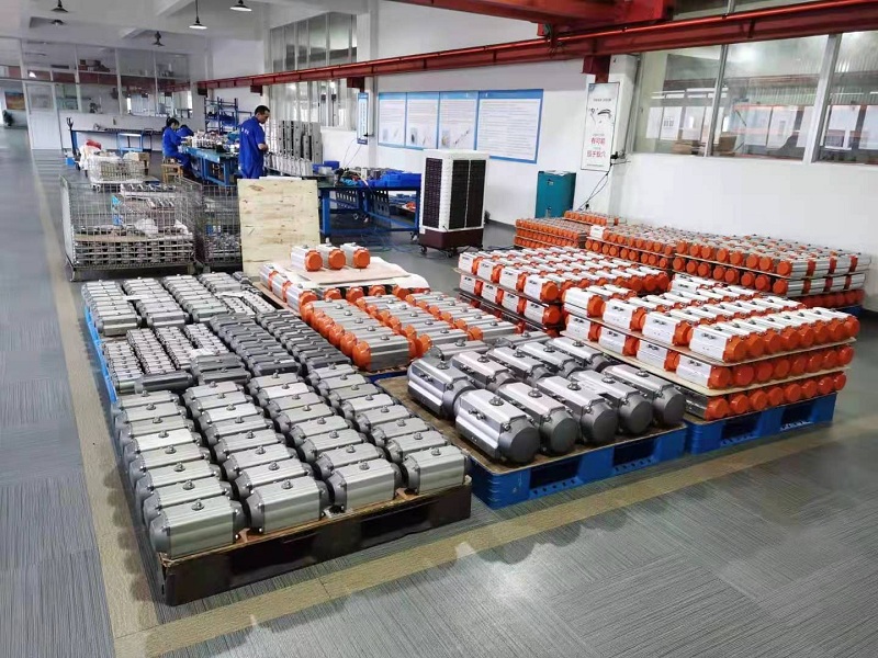
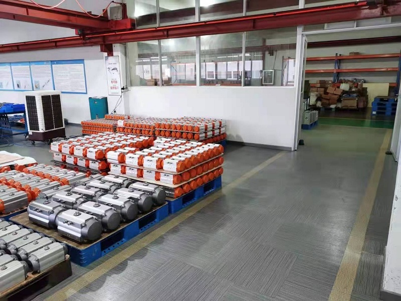
Pneumatic actuator is an actuator that uses pneumatic pressure to drive the open and close or adjust the valve, also known as pneumatic actuator or pneumatic device, but commonly known as pneumatic head. Sometimes pneumatic actuators are equipped with certain auxiliary devices. Commonly used valve positioner and hand wheel mechanism. The function of the valve positioner is to improve the performance of the actuator by using the feedback principle, so that the actuator can achieve accurate positioning according to the control signal of the controller. The function of handwheel mechanism is to operate the control valve directly to maintain the normal production when the control system is power-off, gas stop, controller has no output or actuator fails.
When the compressed air enters the pneumatic actuator from the a pipe nozzle, the gas pushes the double pistons to move in a straight line to both ends (cylinder head end). The rack on the piston drives the gear on the rotating shaft to rotate 90 degrees counterclockwise, and the valve is opened. At this time, the gas at both ends of the pneumatic actuator valve is discharged with the B nozzle. On the contrary, when the compressed air enters the two ends of the pneumatic actuator from the B nozzle, the gas pushes the double plug to move in a straight line in the middle, and the rack on the piston drives the gear on the rotating shaft to rotate 90 degrees clockwise, and the valve is closed. At this time, the gas in the middle of the pneumatic actuator is discharged with a nozzle. The above is the transmission principle of standard type. According to the user's requirements, the pneumatic actuator can be installed with the transmission principle opposite to the standard type, that is, select the right shaft to turn clockwise to open the valve, and turn counterclockwise to close the valve. Single acting (spring return type) pneumatic actuator a nozzle is the air inlet, B nozzle is the exhaust port (b nozzle should be equipped with muffler). The inlet of nozzle a is an open valve, and the valve is closed by spring force when the air is cut off.
The types and structures of regulating mechanisms of pneumatic actuators are almost the same, mainly due to different actuators. Therefore, the introduction of pneumatic actuator is divided into two parts: actuator and control valve. Pneumatic actuator is composed of actuator and control valve. According to the size of the control signal, the corresponding thrust is generated to push the control valve to act. The regulating valve is the regulating part of the pneumatic actuator. Under the thrust of the actuator, the regulating valve produces a certain displacement or angle to directly regulate the flow of fluid.
1. The pneumatic device is mainly composed of cylinder, piston, gear shaft, end cover, seal and screw; The complete set of pneumatic device should also include opening indication, travel limit, solenoid valve, positioner, pneumatic components, manual mechanism, signal feedback and other components.
2. The connection dimension between pneumatic device and valve shall comply with the provisions of ISO5211 (bottom), GB / t12222 and GB / t12223.
3. When the air source is interrupted, the pneumatic device with manual mechanism shall be able to use its manual mechanism to open and close the pneumatic ball valve. When facing the hand wheel, the hand wheel or handle shall rotate counterclockwise to open the valve and clockwise to close the valve.
4. When the end of piston rod is internal or external thread, there should be a suitable wrench port for standard wrench.
5. The sealing ring of piston shall be easy to replace and repair.
Pneumatic device
Pneumatic device
6. For the pneumatic device with buffer mechanism, the stroke length of buffer mechanism can refer to table 1.
7. The pneumatic device with adjustable buffer mechanism shall have a mechanism for adjusting its buffer effect outside the cylinder block.
8. The thread size of cylinder inlet and outlet shall meet the requirements of manur norm sypv, GB / t7306.1, GB / t7306.2 and GB / t7307.
2021-07-09
The first step is to look at the diameter of the cylinder. According to the pressure and the type of load gas, the minimum diameter of the cylinder can be calculated according to the formula.
The second step is to look at the stroke of the cylinder. It's better to roughly determine the stroke according to the stroke ratio and operating distance. With allowance, choose one of the standard strokes to speed up the supply speed.
The third step is to look at the type of cylinder. According to the previous fourth step, it is to look at the installation mode of the cylinder, and choose the installation mode according to where the cylinder is used. Face to determine the diameter and stroke, to choose the right variety, generally choose a brand, safe and reliable.
The fifth step is to look at the buffer mode of the cylinder. Different buffer modes are selected according to the installation mode. Mismatched buffer modes are prone to accidents.
2021-07-05


 Mr. Ran